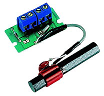
Note: This receiver is no longer available from Conrad! You can however get similar receivers from other suppliers. You may need to change the design of the interface though!
Schematic diagrams (PDF);
Temic T4224 datasheet (PDF) (223 kB)
Start up Google earth. Type: '50° 0′ 56″ N, 9° 0′ 39″ E' <Enter>.
You should now be able to see the
'DCF77' transmission towers.
Now zoom out until you have the position of your receiver on the edge of your
screen. Draw a imaginary line on your screen from DCF77 to your receiver.
The ferrite rod should be in a horizontal plane and perpendicular to this line.
Alignment isn't critical. It works ± 45°. The rod doesn't receive anything from the side, so it's best to point it to a probable interference source;
                           Transmitter


                               ===
Interference          ===============  Rod
source                         ===
| Pin | Signal |
|---|---|
| 1 | GND |
| 2 | Power |
| 3 | + Data |
| 4 | - Data |
The receiver runs on 1.2 ... 15 Volt and consumes ca 3 mA.
3 and 4 are open collector outputs (max 30 V, 1 mA) with opposite polarity;
Pin 3:

    ┌─┐       ┌─┐    open
    │ │       │ │
 ───┘ └───────┘ └─── closed (GND)

Pin 4:

 ───┐ ┌───────┐ ┌─── open
    │ │       │ │
    └─┘       └─┘    closed (GND)

   >   < 0.1 or 0.2 seconds

    <────────> 1 or 2 seconds
One way of using this receiver, is to power it from a USB port;
 2 Ø--*--< + 5 V from USB (Red)
      |
      |
     +++
     | | 6k8
     | |
     +++
      |
      |
 3 Ø--*--> To RXD of RS232 port

 1 Ø--*--> To GND of RS232 port
      |
      +--< GND of USB (Black)

      +--- RS232 Shield
      |
      +--- USB Shield
It's probably a good idea to filter the power a bit (not tested);
           220 Ω
         +-----+
 2 Ø--*--+     +--*--< + 5 V from USB (Red)
      |  +-----+  |
      |           |
      |+         +++
    --+-- 10 µF  | | 6k8
    --+-- 16 V   | |
      |-  Tant.  +++
      |           |
      |           |
 3 Ø--------------*--> To RXD of RS232 port
      |
 1 Ø--*--------------> To GND of RS232 port
      |
      +--------------< GND of USB (Black)

                  +--- RS232 Shield
                  |
                  +--- USB Shield
You could add a LED (not tested);
           220 Ω
         +-----+
 2 Ø--*--+     +--*-------*-----< + 5 V from USB (Red)
      |  +-----+  |       |
      |           |       |
      |+         +++      |
    --+-- 10 µF  | | 6k8  |
    --+-- 16 V   | |      |
      |-  Tant.  +++      |
      |           |   |  /  c
      |           | b |/
      |           *---|    BC548B
      |           |   |\
      |           |   |  \| e
      |           |      -|
      |           |      +++
      |           |      | | 1 kΩ
      |           |      | |
      |           |      +++
      |           |       |
      |           |       |
      |           |     --+--
      |           |      \|/  --> LED
      |           |     --+--
      |           |       |
      |           |       |
 3 Ø--------------*-------------> To RXD of RS232 port
      |                   |
 1 Ø--*-------------------*-----> To GND of RS232 port
                          |
                          +-----< GND of USB (Black)

                          +------ RS232 Shield
                          |
                          +------ USB Shield
Any low power low frequent general purpose NPN transistor can be used instead of the BC548B.
| Transistor | Vce max |
|---|---|
| BC 546 | 80 V |
| BC 547 | 50 V |
| BC 548 | 30 V |
| Suffix | hfe |
|---|---|
| A | 250 |
| B | 300 |
| C | 500 |
The current is just a few mA, so the receiver can also be powered from the serial port. The setup below is designed for a long cable;
 RS232

 9  25   Pins connector

                 3 x 1N4148

                 |\|
 4  20   DTR )---+-+---+
                 |/|   |
                       |
                       |
                 |\|   |
 7   4   RTS )---+-+---*----> + 10 V (less with load applied)
                 |/|   | +
                     --+-- Electrolytic capacitor, 10 µF / 16 V Tantalium
                     --+--
                       | -
 5   7   GND )---------*----> GND
                       | +
                     --+-- Electrolytic capacitor, 10 µF / 16 V Tantalium
                     --+--
                 |/|   | -
 3   2   TXD )---+-+---*----> - 10 V (less with load applied)
                 |\|


 2   3   RXD )--------------< RXD


         SH  ---------------> SH
DTR and RTS provide the positive supply voltage. TXD the negative.
The rectifier circuit fits in a 25 pin RS232 plug.
A 4 wire shielded cable runs between this power supply and the level converter
below;
                  220 Ω
                +-----+
 2 Ø--*------*--+     +--*------*------*------------------*--< + 10 V
      |      |  +-----+  |      |      |                  |
      |      |+          |      |      |                  |
    --+--  --+--        +++     |      |                --+-- 100 nF
    --+--  --+--        | |2k2  |      |                --+--
      | 100  |- 100     | |     |      |                  |
      | nF   |  µF      +++     |      |                  |
      |      |  16 V     |  | |/       |                  |
      |      |           |  |/ - BC    |                  |
      |      |           *--|    558   |                  |
      |      |           |  |\   B     |                  |
      |      |           |  |  \       |                  |
      |      |           |      |  |  /                   |
      |      |           |      |  |/                     |
      |      |           |      *--|    BC548B            |
      |      |           |      |  |\                     |
      |      |           |      |  |  \|                  |
      |      |           |      |     -|           470 Ω  |
      |      |  +-----+  |      |      |         +-----+  |
 4 Ø------------+     +--+      |      *------*--+     +-----> RXD
      |      |  +-----+         |      |      |  +-----+  |
      |      |   15 kΩ          |      |      |           |
      |      |                  |  | |/      +++          |
      |      |                  |  |/ - BC   | | 2k2      |
      |      |                  *--|    558  | |          |
      |      |                  |  |\   B    +++          |
      |      |                  |  |  \       |           |
      |      |                 +++     |      |           |
      |      |           22 kΩ | |     |    --+--         |
      |      |                 | |     |     \|/  -->     |
      |      |                 +++     |    --+-- LED     |
      |      |                  |      |      |           |
      |      |                  |      |      |           |
 1 Ø--*------*--------------------------------*-----------*--< GND
                                |      |                  |
                                |      |                  |
                                |      |                --+-- 100 nF
                                |      |                --+--
                                |      |                  |
                                |      |                  |
                                +------*------------------*--< - 10 V
This circuit consumes ca 1.5 mA (plus the current supplied to the receiver). It drives ca 6 V into a RS232 tester. The LED is optional (not tested yet). BC558B is the PNP complement of the BC548B.
| Transistor | Vce max |
|---|---|
| BC 556 | 80 V |
| BC 557 | 50 V |
| BC 558 | 30 V |
Possible sources of interference;
| Frequency | Harmonic |
|---|---|
| 38.75 kHz | 2 |
| 25.833 kHz | 3 |
| 19.375 kHz | 4 |
| 15.5 kHz | 5 |
TV has a horizontal deflection frequency of 15.625 (EU) or 15.750 (US) kHz.
The 5th harmonic is 78.125 (EU) or 78.750 (US) kHz, which is close to the
DCF's 77.5 kHz. Other possible sources are CRT computer displays.
My receiver doesn't care much about my VGA monitor or my TV. It can't stand my
VT420 though (which ironically is used as a clock; it mimics a 7-segment display
by means of reverse video spaces). The VT420 has a horizontal deflection
frequency of ca 38.5 kHz (which is rather high). The 2nd harmonic (77 kHz) is
rather close to 77.5 kHz. Hence the need for a long cable.
The entry for a refclock in ntp.conf is;
server 127.127.Type.Unit_Number
In this case you need the Generic Reference Driver mode 5
Add the following to ntp.conf;
# Conrad DCF77
server 127.127.8.0 mode 5
fudge 127.127.8.0 time1 0.220 refid DCF77a
You may need to change the time1 value.
The GENERIC driver wants a symlink in /dev/ telling it which is the source of the time. EG ttyS2;
refclock-0 -> ttyS2
created a file '77-local.rules' in '/etc/udev/rules.d/' for this purpose. It contains the following line;
KERNEL=="ttyS2" SYMLINK+="refclock-0"
Replace 'ttyS2' with the tty you use.
I had trouble using this with a
multi serial card.
Running it on a standard RS232 port works fine.
This may have something to do with fact that 200 ms pulses cause framing errors;
Normal data; One startbit (0), 8 databits (0 or 1), one stopbit (1);
   ─────┐   ┌───┬───┬───┬───┬───┬───┬───┬───┬─────────
        │ S │ 0 │ 1 │ 2 │ 3 │ 4 │ 5 │ 6 │ 7 │ S
        └───┴───┴───┴───┴───┴───┴───┴───┴───┘
          .                                   .
         /|\                                 /|\
          |                                   |
          Check; Is bit 0?                    Check; Is bit 1?
          If not; Framing error               If not; Framing error
Data from DCF reciever;
A '0' is coded as a 100 ms pulse (the ports reads 240 / 0xF0);
   ─────┐                   ┌─────────────────────────
        │      100 ms       │
        └───────────────────┘
A '1' is coded as a 200 ms pulse (the port reads 0);
   ─────┐                                       ┌─────
        │                 200 ms                │
        └───────────────────────────────────────┘
                                              .
                                             /|\
                                              |
                                              Framing error
If this is the case limiting the pulse length to 180 ms will solve the problem; The port still reads 0, but without framing errors.
Currently NTPD uses parity, resulting in parity errors instead;
   ─────┐   ┌───┬───┬───┬───┬───┬───┬───┬───┬───┬─────────
        │ S │ 0 │ 1 │ 2 │ 3 │ 4 │ 5 │ 6 │ 7 │ P │ S
        └───┴───┴───┴───┴───┴───┴───┴───┴───┴───┘

   ─────┐                   ┌─────────────────────────────
        │      100 ms       │
        └───────────────────┘

   ─────┐                                       ┌─────────
        │                 200 ms                │
        └───────────────────────────────────────┘
I added low latency to the setserial config;
/dev/ttyS0 uart 16550A port 0x03f8 irq 4 baud_base 115200 spd_normal skip_test low_latency
/dev/ttyS1 uart 16550A port 0x02f8 irq 3 baud_base 115200 spd_normal skip_test low_latency